Packaging type
Size: L100 x W85 x H20 mm,Architecture:Metal outer seal,Optical output:OPTICAL INPUT,Electrical signal output:SMA,
Electrical interface:DC+5V

Pulse Photo-diode Module
Packaging type
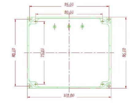
Size: L100 x W85 x H20 mm
Architecture: Metal outer seal
Optical output: OPTICAL INPUT
Electrical signal output: SMA
Electrical interface: DC+5V
Electron optics parameters
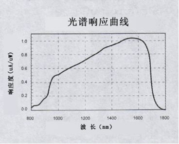
参数 Parameter 最小值 Min 典型值 Typ 最大值 Max 工作波长(nm) Operationwavelength 900 1700 响应度(A/W) Responsivity 0.85 光纤类型 Fiber type Corning SMF-28e 光纤接头 Fiber optic connector FC/APC 放大倍数(V/W) magnification 2000 最大承受光功率(mW) Maximum optical power 5 10 暗电流(nA) Dark Current 1 模块总带宽(MHZ) Total module bandwidth DC 330M 探测光功率范围(mw) Detect optical power range(mw) 0.002 2 模块工作电压(DCV) Module operating voltage(DCV) 5 模块工作电流(DCA) Module operating current(DCA) 0.2
Module Overview
The photoelectric detection module integrates a single mode fiber coupled InGaAs photodetector internally, and the internal amplification circuit adopts a combination of high magnification and noise suppression technology to improve the signal-to-noise ratio and obtain high-quality output signals for the subsequent data acquisition card. The detector module adopts a single power supply of DC+5V, which generates negative pressure and PD bias internally. It has high integration and is convenient for customers to use. Output voltage signal, output interface is SMA, and equipped with SMA to BNC RF cable.
Operating steps
1) There is a power socket on the photodetector module. Please connect the input end of our company's standard power module to this power socket. You can see that the power indicator light is on, indicating that the source block has been powered on and is working properly.
2) Connect the optical signal to the fiber optic connector, connect the module output SMA connector to the corresponding acquisition card or oscilloscope, and debug the corresponding light source signal to observe the collected waveform.
3) After use, turn off the input light source and disconnect the DC+5V power supply.
Attention
1.Before starting up, please confirm that you are using a DC+5V power supply and do not exceed the usable voltage range. Please use our company's standard power module
2. If the power indicator light is on, it indicates normal power supply. If the light is not on, please check if the connector is in good contact
3. To prevent strong light input from damaging the photodetector, the input light power should not exceed 5mW. If the input light power is unknown, please add attenuation first
4. The DB9 interface is a factory debugging port, which is not defined at the factory and is not required by users.
Panel diagram

Attachment: Spectral Response Curve Graph
Dimension

 QQ在线咨询
 0816 - 2384466