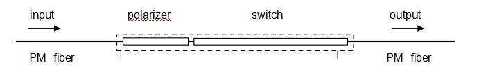
All-fiber type polarization switch
Product Overview
ZG Photonics polarization switch enables the conversion of an input linear state aligned on the input polarization maintaining fiber axis to be switched between either of the orthogonal output axes. For example an input on the slow axis can be converted to the fast axis at the output or modulated between the fast and the slow axis. This device has been designed to be flexible and easy to operate requiring only a controlled current source for applications in which control of polarization between orthogonal states is required.
Features
An in-line fiber polarizer integrated at the input to provide a highly linear polarization state is optional.
Option 1 Standard(This version allows switching between either axis of the output fiber for a single axis input.)

Option 2 Integrated polarizer(This option includes an integrated fiber polarizer in front of the waveplate aligned to the slow axis of the input fiber. The role of the polarizer is to ‘clean’ the linear input state. )
Performance Parameter
规格Specification 单位Units 规格一 Option 1 规格二 Option 2 波长范围Wavelength range nm 1300 - 1610 插入损耗Insertion Loss dB <0.5 <1 消光比Polarizer extinction ratio dB - >30 回波损耗Return Loss dB >70 >70 Maximum current mA 70 最大电压Maximum Voltage V 10 开关时间Switching time s <1 <1 工作温度Operating Temperature ℃ -5 to 70 -5 to 70 贮存温度Storage Temperature ℃ -40 to +85 -40 to +85 光纤类型Fiber type PANDA PANDA 输入&输出光纤长度Input & Output Fiber Lengths mm 1000 1000
Specification Notes:
1.Devices will operate over full wavelength range, higher current is required at longer wavelengths to achieve switching.
2.Insertion loss for option 2 assumes on-axis alignment of the input polarization. Losses do not include connectors.
3.Extinction ratio is defined as the PDL of the input polarizer
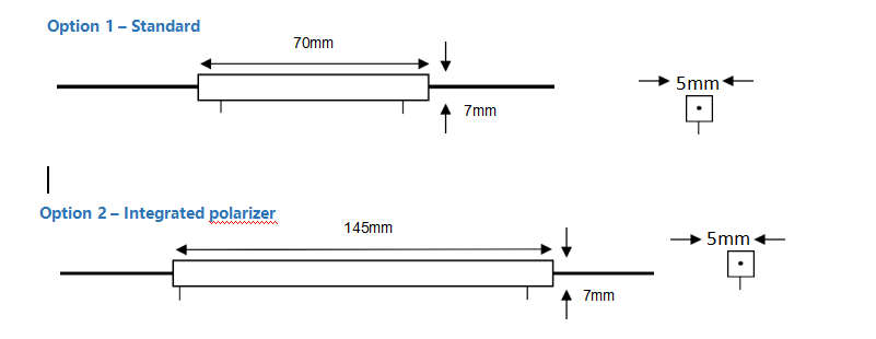
dimension
Ordering information
选项Option 波长Wavelength 连接头类型Connectors 光纤类型Cable type 01- standard 02- polarizer 15 – 1530 – 1610 nm 14 – 1480 - 1530 nm 13 – 1280 - 1330 nm 0 – none 1– FC/SPC 2– FC/APC 0– none 1– 900mm loose tube

 QQ在线咨询
 0816 - 2384466