850nm Multi-mode Electrically Controlled Variable Optic Attenuator
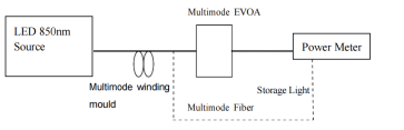
1.DESCRIPTIONZg introduces a new miniature variable attenuator for application in either the C or L band. The attenuator offers excellent wavelength dependence and ripple, low polarization dependent loss (PDL), and improved thermal stability. The attenuator provides an economical solution to managing optical power. Reflective optics permit same-side jumper exit and enable easy panel mounting. The attenuator uses an advanced graded neutral density filter as its attenuating element. Adjustment is through a stepper motor with feedback control terminal. The driver for the stepper motor moves the motor up or down in uniform step sizes, offering fine resolution. Latching operation is a standard feature; upon removal of the drive voltage, the most recent attenuation setting is retained. An optional resistance readout for filter location purposes is available. The schematic figure of the attenuator is shown in figure 1.

Figure 1 Functional Scheme
2 . OPTIC AND/OR ELECTRIC SPECIFICATION
Optical
Parameters | Value | Unit | Note |
Wavelength range | 800-1100 | nm |
|
Attenuation range | 30 | dB |
|
Response speed @ adjustment attenuation resolution | 100 | ms | Voltage drive mode |
Attenuation resolution | 0.2 | dB | Full step |
Lock stability | 0.3 | dB | According to motor power switch |
Insertion loss | 1.0 | dB | With connector, within wavelength range |
Attenuation linearity | 5 | % | 30dB@±0.5dB |
Repeatability | 0.1 | dB | Difference in attenuation when returning to a specific attenuation from a random position approached from the same direction. |
Recoil | 0.2 | dB |
|
Return loss @ input/output | -25 | dB | Note: Attenuation value at a specific voltage/step may vary over time and will vary with units |
Polarization-dependent loss @ input/output | 0.5 | dB |
|
Temperature-dependent loss | 0.5 | dB | With connector |
Polarization mode dispersion @ input/output | 0.15 | ps |
|
Carrying optical power | 300 | mW | CW |
Test method
Step motor electrical specification
Parameters
| Value | Unit | Note | ||
MIN | TYP | MAX |
|
| |
Motor type | Step motor, 2-phase motor |
|
| ||
Motor current |
| 150 | 200 | mA | 2-phase on |
Recommended DC control voltage | 3.0 | 3.3 | 3.6 | V | Full step and both coils are powered |
Pulse width per step | 1.25 | 2.0 |
| ms |
|
Motor resistance |
| 20 |
|
|
|
Motor power consumption |
|
| 2 | W | In the temperature range of -5~70℃ |
Absolute maximum limit value
Parameters | Value | Unit |
Operation temperature | -5 ~ +70
| °C
|
Operation humidity | 5 ~ 95
| %RH
|
Storage temperature | -40~ 85 | °C
|
Electrical interface definition
Pin | Definition | Describe | Note |
1 | Motor Coil A |
|
|
2 | Motor Coil B |
|
|
3 | Motor Coil B |
|
|
4 | Motor Coil A |
|
|
5 | Monitor Signal | POT wiper, movable contact: voltage sensor. |
|
6 | Monitor Supply + |
|
|
7 | Monitor Supply - | POT + connected to a stable (reference) positive power supply |
|
8 | Ground |
|
|
9 | None |
|
|
10 | None |
|
|
11 | None |
|
|
12 | None |
|
|
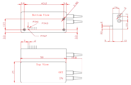
Drawing
Pigtails and Connectors
Parameters | Specifications | Unit | Notes |
Pigtail type (all ports) | 62.5/125nmor50/125um |
| According to customer requirements |
Pigtail length (all ports) | L+/-0.1 | m | L refers to the fiber length requirement in PN |
Connector type (all ports) | According to customer requirements |
|
|


 joe@zg-photonics.com
 0816 - 2384466