Definition
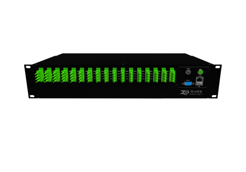
The switch matrix is an optical switching device manufactured based on micro-electromechanical system technology. It has 16 input ports and 16 output ports, enabling flexible switching and configuration of optical signals between any input port and any output port. Its working principle mainly relies on the precise movement of micromirrors or microrotors in the micro-electromechanical system.
Feature
Port configurable
Supports any port interconnection
Backup port protection
Supports software-defined packet
Optional adjustable attenuation
Optional low-frequency switch modulation
Application
Full optical switch
Optical link protection
Automation testing
Network monitoring
Automatic fault location
Specification
Operation environment
Parameter | Min | Max | Unit | Remarks |
Operating Temperature | -5 | 70 | °C |
|
Storage Temperature | -40 | 85 | °C |
|
Operating Relative Humidity | 5 | 95 | % | Under non-condensing conditions, the moisture content shall not exceed the industrial standard of 0.024 kg of water per kg of dry air |
Storage Relative Humidity | 5 | 95 | % |
Specification
Parameters | Spec | Unit | Note | ||||
Number of channels | ≤32 | ≤68 | ≤132 |
|
| ||
Operation wavelength range | 1260-1660 | nm |
| ||||
Typical insertion loss | 1.7 | 2 | 3 | dB | applicable to device with LC/PAC connector | ||
Maximum insertion loss | 2.5 | 3 | 3.5 | dB | applicable to device with LC/PAC connector | ||
Crosstalk | >45 | dB |
| ||||
Return loss | >50 | dB | applicable to device with LC/PAC connector | ||||
Polarization-dependent loss | <0.2 (C or L Band) | dB |
| ||||
Wavelength-dependent loss | <0.3 (C or L Band) | dB |
| ||||
Durability | >109 | Cycles | Design Assurance | ||||
Repetition | ±0.1 | dB |
| ||||
Switching time | <50 | ms | Design Assurance | ||||
Fiber optic type | G.657 A2 |
|
| ||||
Case size | 2U rack | 4U rack |
|
| |||
Connector type | LC/APC |
| Customize | ||||
Control | RS232 / USB |
|
| ||||
Power consumption | <8 | <15 | <30 | W |
| ||
Power supply | 100-240VAC 50/60 Hz or48 VDC |
|
| ||||
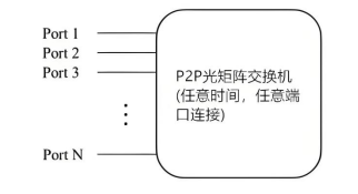
Functional diagram
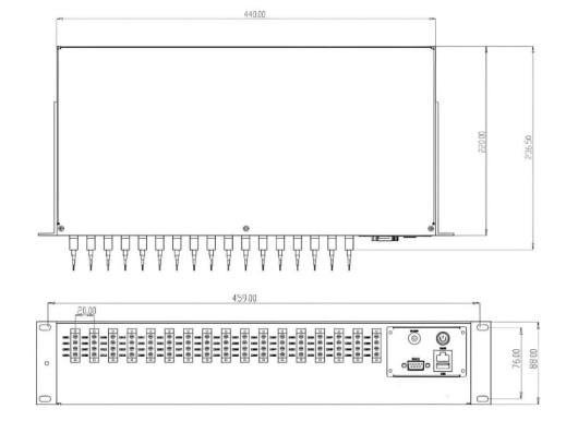
Dimension
Ordering info
ZG | Channel no. | CWL | Fiber type | Connector | Case |
32=32CH 68=68CH 132=132CH XX=others | 1260=1260nm 1660=1660nm XX=others | G.657 A2 | LC/APC | 2U 4U |

 joe@zg-photonics.com
 0816 - 2384466